Difference between revisions of "Assembling the Mixer"
| Line 37: | Line 37: | ||
[[File:Inside mixing container..jpg|center|50px|thumb]] Straight down picture showing the rubber stopper. Notice that the tubing could be lowered in the stopper to facilitate better draining. | [[File:Inside mixing container..jpg|center|50px|thumb]] Straight down picture showing the rubber stopper. Notice that the tubing could be lowered in the stopper to facilitate better draining. | ||
| − | + | [[File:Mixing container bracket work.jpg|thumb]] This image shows the mixing container inside the other support bottle. You can also see the paper towels we stuff between the 2 to help support the inner mixing container. | |
Now you will need to mount or support the mixing container on the rigid backing that can also support the mini-lathe motor which provides the stirring action during the mixing phase. The bottom of the plastic bottles should be cut off so that a funnel is created. The larger (outer) funnel will contain the inner funnel and support it. Without this approach, the inner funnel would need a complicated mounting system or be punctured with wood screws to attach to the backing. Having the larger funnel-bottle support the mixing container is easiest as it can be attached with whatever and doesn't need to avoid leaks. It may not look nice but that was never the design goal. This was our first attempt and we're still happy with it. Also - there are paper towels between the 2 funnels. This helps steady the inner funnel. | Now you will need to mount or support the mixing container on the rigid backing that can also support the mini-lathe motor which provides the stirring action during the mixing phase. The bottom of the plastic bottles should be cut off so that a funnel is created. The larger (outer) funnel will contain the inner funnel and support it. Without this approach, the inner funnel would need a complicated mounting system or be punctured with wood screws to attach to the backing. Having the larger funnel-bottle support the mixing container is easiest as it can be attached with whatever and doesn't need to avoid leaks. It may not look nice but that was never the design goal. This was our first attempt and we're still happy with it. Also - there are paper towels between the 2 funnels. This helps steady the inner funnel. | ||
Revision as of 19:43, 9 August 2024
RAMPS boards
Assemble the RAMPS board. There are numerous instructions on the internet. Youtube works the best but you should be able to find an appropriate howto.
You may or may not need to recompile a version of Marlin. (RAMPs OS) It depends on which display is integrated into your RAMPS board. There may also be an issue with the end-stops. As of 8/3/24 it is unknown as far as what is required. In general as long as the RAMPS board doesn't auto-cut off due to the end-stop state, and the display displays, then you should be good to go.
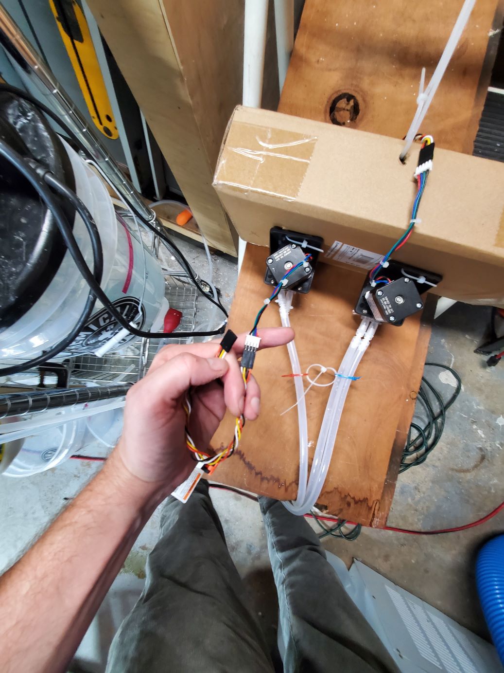
Blurry picture showing the header pins needed to connect the power extension
Here is a blurry picture of the header pins. They pins stick out from both sides but it isn't clear.
Pumps
How you mount the pumps is up to you. We mounted ours horizontally but I would suggest mounting then vertically to reduce the space footprint. Horizontal also allowed us to place the electronics above all the liquids. We used zip-ties but wood screws would work better. There are no real forces on the stepping motors so zip-ties seemed sufficient but might be a safety issue if they were to break and fall. Just drill 2 holes to loop the ziptie through, possibly using 2 ties connected to form 1 longer-ziptie. The zip-tie also seems more reasonable when they are mounted horizontally as the zip-ties only keep the pump from sliding horizontally and are not actually supporting the weight
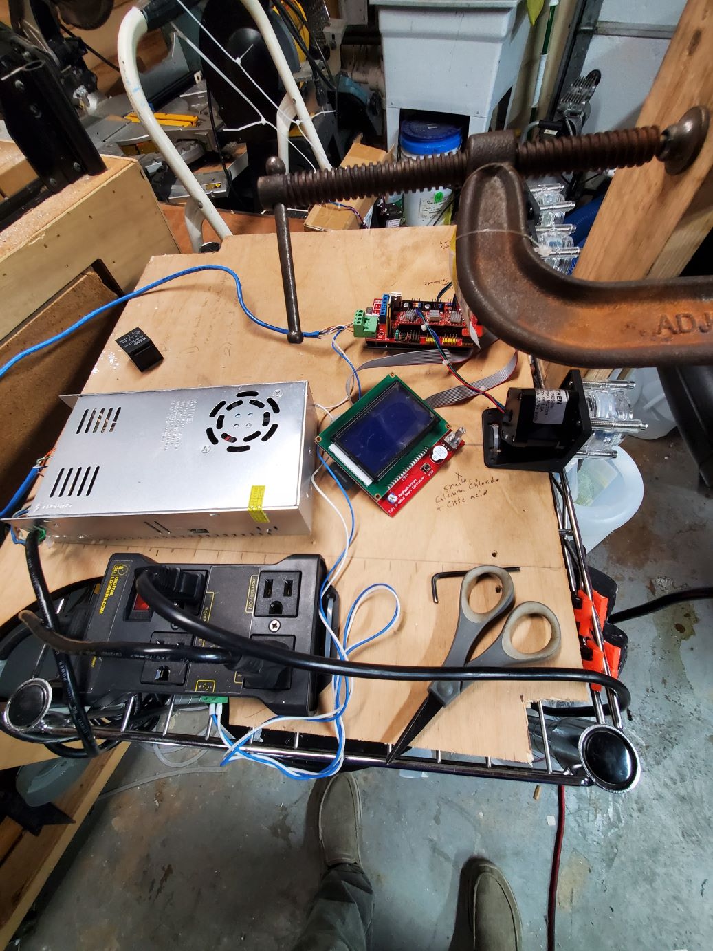
This is just a snapshot of our original prototype board. Ignore the 110 AC relay which we used for an original iteration that powered a drill. The other 2 pumps are obscured.
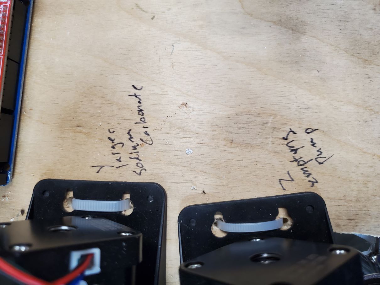
Example of our zip-tie usage. (not recommended)
Each pump is attached to the appropriate axis on the 3d printer board. A 3d-printer has 3 axis, one for X Y Z.
- X - Calcium Chloride + Citric Acid
- Y - Sodium Carbonate
- Z - The output from the mix container.
After mounting the pumps I went ahead and labeled the axis and ingredient going to the pump. Determine where you want to keep the input buckets during the mixing stage. Cut the tubes to reach from the bottom of each input bucket to the input on the pump. Push the hose onto the pump. If facing the pump, the motor should rotate clockwise if everything is oriented properly.
Mixing Container
We used 2 similar but different sized recycled plastic bottles. With the larger outer bottle one mounted by wood screws. This one provides support for the actual mixing container. (Without the need for puncturing the mixing container.)
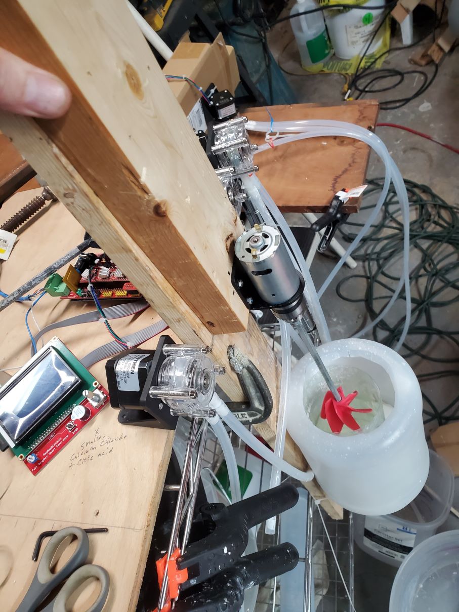
Picture of above showing an overview.
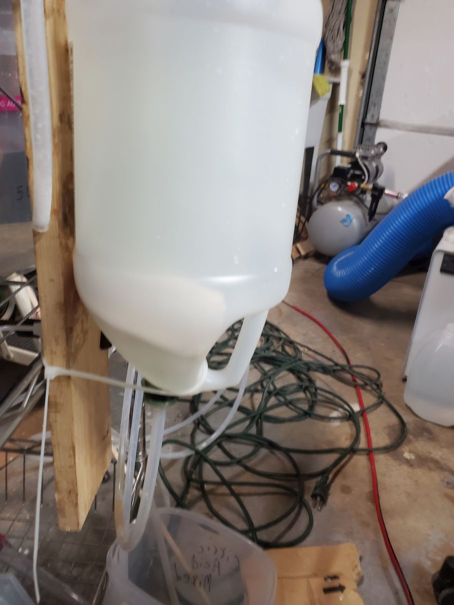
Side picture of the bracket to show how the bottle bracket was supported.
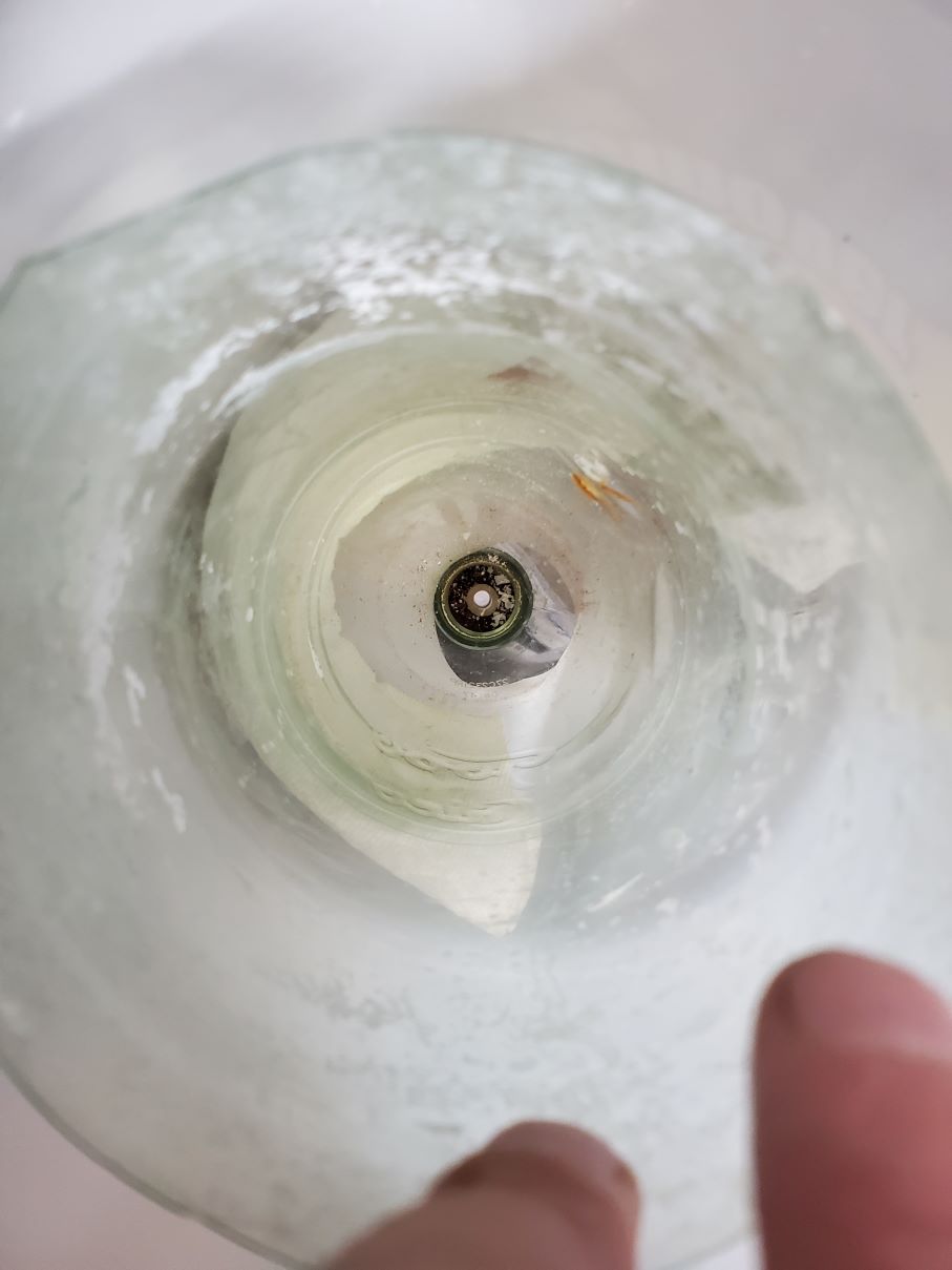
Straight down picture showing the rubber stopper. Notice that the tubing could be lowered in the stopper to facilitate better draining.
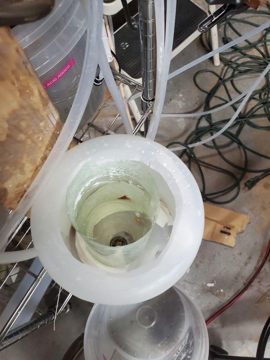
This image shows the mixing container inside the other support bottle. You can also see the paper towels we stuff between the 2 to help support the inner mixing container.
Now you will need to mount or support the mixing container on the rigid backing that can also support the mini-lathe motor which provides the stirring action during the mixing phase. The bottom of the plastic bottles should be cut off so that a funnel is created. The larger (outer) funnel will contain the inner funnel and support it. Without this approach, the inner funnel would need a complicated mounting system or be punctured with wood screws to attach to the backing. Having the larger funnel-bottle support the mixing container is easiest as it can be attached with whatever and doesn't need to avoid leaks. It may not look nice but that was never the design goal. This was our first attempt and we're still happy with it. Also - there are paper towels between the 2 funnels. This helps steady the inner funnel.
Drill out the stopper and insert the tubing into it. Look at the "O.D. outer-diameter on the tubing you purchased. Try a drill bit of that size but if in question try a smaller one first. That way you won't drill too big of a hole and ruin the stopper. Make it so that the tubing does not protrude past the top of the stopper. (This would create an area that won't drain and the pictures above seem to demonstrate this issue) Push the stopper into the neck of the mixing container. It should form a water tight seal inside the mixing container's neck.
Lathe motor
Above the funnel and utilizing the same backing for mounting, you will need to attach the lathe motor.
You will need to assemble the lathe motor with the chuck and bracket. It should have a L shaped mounting bracket included but the lathe motor was never meant to be vertical. It was meant to have the wood stock have a constant pressure pushing into the motor. This would keep the bronze sleeve from ever slipping off and having the chuck detach from the motor. We used blue Loctite although had red loctite been sitting around I would hvae tried that.
First - make sure to attach the bracket to the motor. Otherwise you will not be able to access the screws to mount the motor onto the bracket (The chuck is applied permanently and blocks it). We would suggest loctite during this stage to help ensure it won't separate.
After the bracket has been attached - insert the motor in the bronze sleeve. We will use a torch for this but did not determine how needed the torch actually is. It wound up boiling the loctite which was concerning. We also froze the motor to shrink the shaft (unlikely to have mattered). Find an anvil like surface which you will rest the bronze sleeve on. Find some needle-nose vice-grips and have it comfortably grip the bronze sleeve while allowing the bronze sleeve to lay flat on the anvil surface. Now heat up the bronze sleeve with some form of a torch and get it reasonably hot. We applied loctite to the heated sleeve the the Loctite boiled off under our nose. Yuck. You may wish to try it without loctite or without a torch.
Once the bronze is significantly heated - take the motors' axle and lightly tap it into the bronze sleeve with a small hammer. I've done this twice and the first time was real smooth and the 2nd one required more force. Just make sure you hammer on the axle and not the motor casing. It is the most intuitive to hold the motor with your fingers and the sleeve with vice-grips and then lightly tapping the axel that sticks out the motor. Having the motor on the anvil and hammering the sleeve might be better. If you need to tap harder - I would suggest holding the sleeve with pliers and resting the axle on the anvil-like surface while being held up with some sort of clamp. This way did seem to work easier.
Apply Loctite to the sleeve and lightly tap the chuck on. This really wasn't meant for much force and is designed for the chuck to slide off. This part should really have Loctite applied so it doesn't separate in the future. I would go ahead with Red Loctite.
This should have all the parts from the lathe kit assembled and ready to mount onto the wood back.
Now you will need to mount the lathe motor to the backing. The centering doesn't seem necessary, in fact it might be better to not having the motor axle centered in the mixing funnel. Having it offset might increase the turbulence and thus be beneficial. For the sake of consistency we have tried to keep the motor's axle aligned with the center of the funnel. The L bracket should be used for this but you will need to find a shim to mount between the backing and the L bracket. The bracket holds the lathe motor to close to the surface to not use a shim (spacer?)
You will need to create a block of wood tp be the correct height for the shim. You want to have the lathe motor coaxial with the mixing container. The shim is between the motor bracket and the wood with the mixing container mounted. This thickness of the wooden shim/spacer depends on what you used as your mix container. This aspect could be a bit problematic if you don't have access to a planer but it doesn't need to be anywhere near perfect. The main aspect is that the stirrer does not rub against the walls of the container. You also want to have the stirrer low enough to thoroughly stir the solution.
I had access to a planer so was able to plane down a piece of 2x4 into the appropriate height. This part actually needs to be somewhat well supported compared to the pump motors. I do not feel zipties would be appropriate. The lathe motor L bracket has 4 holes to mount it to a surface. Unfortunately with a permanently installed chuck - the screw holes are obscured. This means you can not use woodscrews. Instead, you will need to drill out some small holes and use m3 machine screws. We wound up using ones that were 35mm long but they were barely long enough. They required we counter-set them with a hammer. Then we had to use a fine needlenose vicegrip or an industrial tweezer. I suspect you could also use your finger, but you will need to hold the nut on to get it started initially.
We used wood screws and attached the shim to the backing. This also allows the lathe motor to be adjusted vertically by detaching the shim from the backing.
When placing the L bracket, insert the paddle you are going to use into the chuck and adjust the height so that the paddle is barely clearing the bottle-funnel. The closer it is to the bottom of the bottle - the less likely there are lower areas in the mixing container that are not being properly stirred.
Once this is done go back to your tubing. Attach the tubing to the pumps and cut it to a length where it stick a few inches into the mixing container. It just needs to be deep enough to not fall outside of the mixing container. (And leak the input solution all over)
Run the xyztest.gcode to see which way your pumps pump. Then push the input tubings to the appropriate spot. The gcode expects a certain direction. (can you change the power?)
