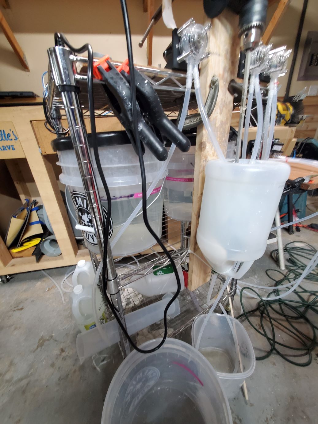
Assembling the Rinser
This is empty and after assembling the the mixer this is fairly straight forward. 2 pumps. 1 pumps clean water from a larger reservoir for each rinse cycle. The other pump pumps out the salt water into the drain or another container for a different disposal.
There is also the lid that sits on top of the bucket. Actually - here are the first draft instructions. They have not been editted.
This will be a simple wooden lid that sits on top of the bucket and holds the lathe motor to briefly mix the fresh water before it is allowed to settle. Ideally you will just move the bucket from the mix stage and put this lid on it to continue the process.
If you have not assembled the second RAMPs board, go ahead and do that.
Figure out how you wish to mount the 2 pumps.
Connect the other 2 stepping motors/pumps to the X and Y axes. The X axis is used to pump fresh water in and the Y axis will empty the extra water into a sink. This is not necessarily acceptable for longterm use. We didn't research how much of an issue it is to dump salt water into the sewer system.
Go ahead and cut the 2 conductor wire meant for the lathe motor. It will need to reach from the RAMPs board to the top of your rinse bucket. It will need to be wired up like it was for the mixer.
You will be cutting 4 pieces of tubing.
Cut the tubing to reach from the bottom of your large fresh reservoir to the pump. Then from this pump to the rinsing bucket.
The other pump will drain the bucket after the pigment has settled.
You will need to create the outlet for inside the rinse bucket. It has to be rigid and stay in one stationary place throughout the process although it has no force applied to it during the process. Simple clamps will suffice. The inlet of the outlet (hah!) needs to be placed as close to the surface of the settled pigment as possible. So when it pumps water out, it leaves the settled pigment behind and undisturbed.
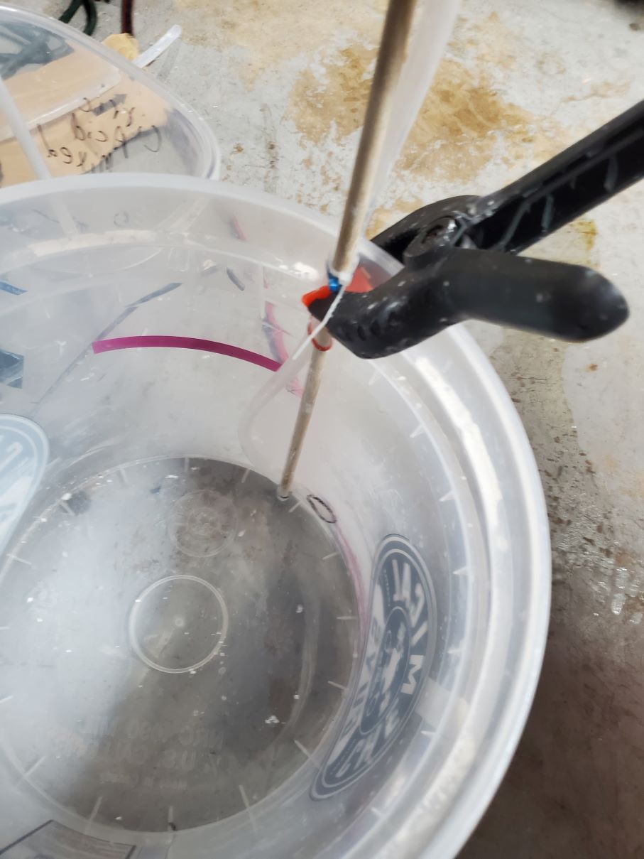
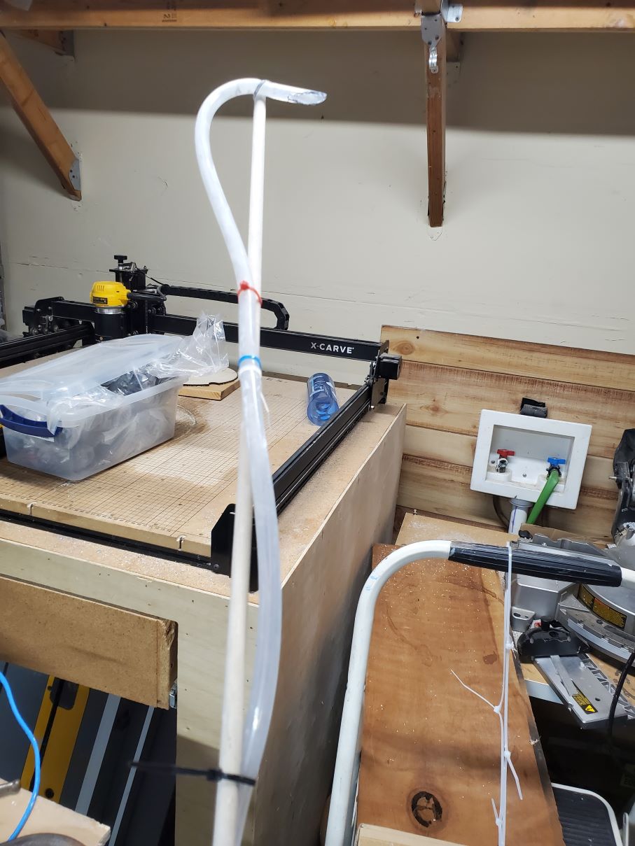
The way I did it was to take a wooden dowel and ziptie the tubing to it. Then the dowel can be clamped to the bucket at the top and the rigidness will hold the hose where it needs to be during the decanting process. You'll want to keep the clamp out of the salt water but most clamps would not work anyway. It would need a specialized clamp with a deep jaw to be able to clamp at the bottom of the bucket. So instead we ziptie the tubing to the wooden dowel and clamp the dowel at the top of the bucket.
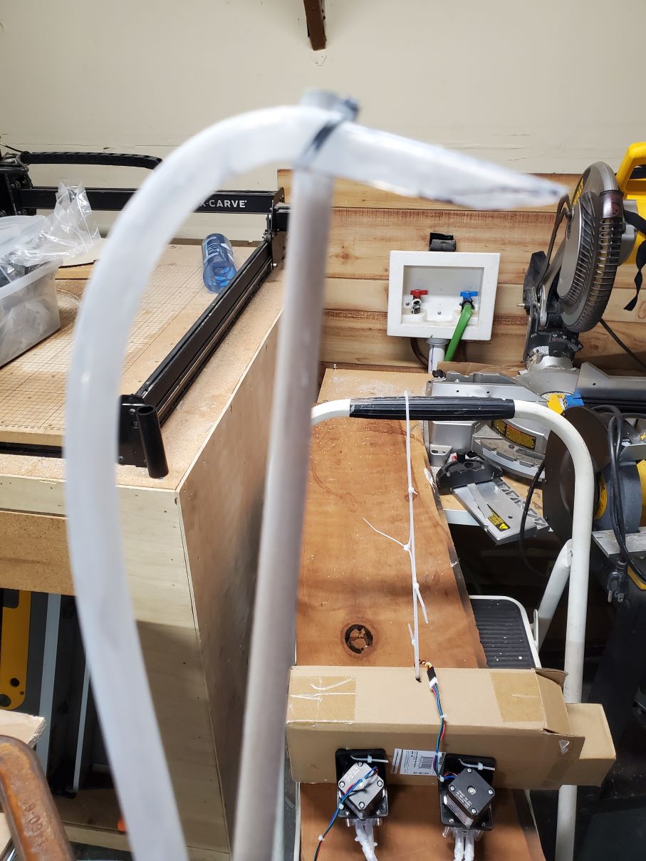
We turned the inlet upside down because it seems like it might disturb the liquid less but I'm skeptical of that. Having the hose point downward likely works just well and the pigment won't settle into the hose which is what happens when it is turned upwards.
You should hold off on the position on the dowel until after you have done a full mixing stage and let it settle out for 4+ hours. You might be able to get away with less but the longer you wait the clearer the salt water will be which helps you visually see where the hose inlet is within relation to the pigment. We took a black sharp and colored over the end of the tube so that it had a contrast with the surface of the pigment. We also had a transparent bucket so we could readily see where the edge of the hose was in relation to the settled pigment under it. If you're too high then the rinses just aren't quite as efficient at removing the salt since you're not getting as much salt water out during the batch. You will however not waste pigment by making the hose too high.
Go ahead and attach the tubing to the 2nd pump (hooked up to the Y axis). The last bit of hosing will be to pump off the salt water. We placed the hose in the sink. If you have metal sink stuff you should probably not let the salt water sit around after being pumped into the sink. I would suggest a decent flush.. Although salt water is not toxic it is corrosive and can kill plants.
Now you will need to create the bracket for the other lathe motor. This motor will turn for a bit to fully disturb the pigment at the bottom of the bucket which is needed to have the salt evenly dispersed throughout the rinse water. The way we did it was to make the device sit on top of the bucket using a wooden lid made out of 1x4 or 2x4s. I am referring to it as a lid-cross from here. The lid-cross will be wide enough that it sits on top of the bucket. I'd suggest a couple of inches of overshoot. Take the lid-cross, center it, then on the bottom of the lid, mark with a sharpy where the edge of the bucket was touching the lid-cross.
You will now apply 4 small blocks of wood on the bottom side of the lid-cross. You can put these blocks so that they rest on either on the inside or outside of the bucket. (Do them all in the same manner). Either way should prevent the lid-cross from slipping on or off the bucket but it is up to you to determine the safety. Remember - does have salt water (conducive) with electrical things above it. So making sure the lid won't slide is important.
Now you will need to mount the second lathe motor to the cross. As the cross sits on top of the bucket, it will support the padde/lathe motor above the water so that after ever refill, the bucket can be stirred. There is no need to dissolve anything, just to make sure the fresh water rinses all the pigment. You'll likely need a larger drill bit to allow the paddle to fit through the cross into the chuck.
Now hook up the 2 conductor wire from the lathe motor to the ___ on the RAMPS board. The rinser doesn't really need calibration. The amount to pump out is determined by the what was specified in the gcode generator for the mixer. If you have different types of pumps then you will need to calibrate the process for those pumps. If everything else is the same - the calibration for the mixer stage should be sufficient.
Ideally we will just remove the tube the output bucket for the mixing stage and place the cross-lid on top of it. Run the rinse.gcode which will do the pausing/settling/rinsing for you. After it is done you will have pigment that is semi-suspended in water which will then need to be dried.
This allows the decanter inlet to have an adjustable height so that it is just right about the settled pigment layer. (and thus only sucks out salt water - leaving the pigment layer behind)
This is the zip-tied decanting hose seen outside the bucket. We inverted the opening to point up in hopes that it doesn't disturb the pigment right beneath it. Whether this is a good idea or not we're unsure. Notice the black market applied to the tip to give the end of the tube constrast against the white pigment.
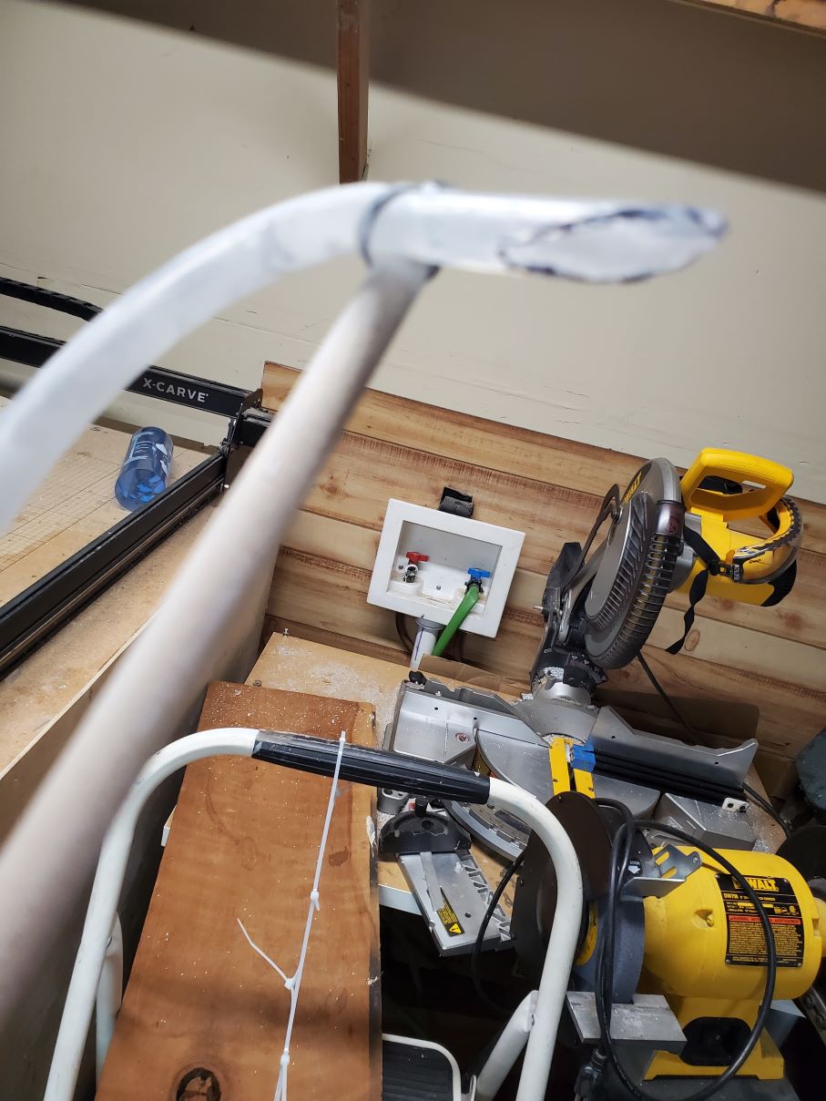
We made it wider so that the pump rate would be lessened at the very tip of the inlet. Again - this is an attempt to not disturb the pigment under it. Notice the black marker.
Just another close-up
Finally here is the finished version of the first mixer prototype. The input buckets have the hoses removed so that the lids would fit. THis is also the first design which used a drill powered by a relay. It does show the positioning of the 3 buckets which is not something we are changing.
